Home /
Expert Answers /
Electrical Engineering /
figure-1-shows-circuit-of-modulation-technique-the-circuit-is-comprised-of-power-supply-resistan-pa382
(Solved): Figure 1 shows circuit of modulation technique. The circuit is comprised of power supply, resistan ...
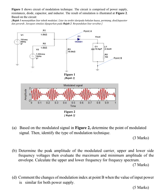
Figure 1 shows circuit of modulation technique. The circuit is comprised of power supply, resistances, diode, capacitor, and inductor. The result of simulation is illustrated at Figure 2. Based on the circuit: [Rajah 1 menunjukkan litar teknik modulasi. Litar itu terdiri daripada bekalan kuasa, perintang, diod,kapasitor dan peraruh. Jawapan simulasi dipaparkan pada Rajah 2. Berpandukan litar tersebut:] V1 1Vrms 50Hz 0* Amplitude V2 R1 1.0kg R2 ww 1.0k 1.5Vrms 1kHz 0° R3 10.0k D1 1N4001 Figure 1 [Rajah 1] Modulated signal Figure 2 | Rajah 2] Point A Vout C1 L1 :10.0pF 2.5mH R5 10 0.1 0.2 0.3 0.4 0.5 0.6 0.7 0.8 0.9 Time Point B (a) Based on the modulated signal in Figure 2, determine the point of modulated signal. Then, identify the type of modulation technique. (3 Marks) (b) Determine the peak amplitude of the modulated carrier, upper and lower side frequency voltages then evaluate the maximum and minimum amplitude of the envelope. Calculate the upper and lower frequency for frequecy spectrum. (7 Marks) (d) Comment the changes of modulation index at point B when the value of input power is similar for both power supply. (5 Marks)