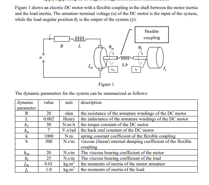
(Solved): Figure 1 shows an electric DC motor with a flexible coupling in the shaft between the motor inertia ...
Figure 1 shows an electric DC motor with a flexible coupling in the shaft between the motor inertia and the load inertia. The armature terminal voltage (u) of the DC motor is the input of the system, while the load angular position
\theta _(l)is the output of the system
(y). The dynamic parameters for the system can be summarized as follows: \table[[\table[[dynamic],[parameter]],value,unit,description],[R,20,ohm,the resistance of the armature windings of the DC motor],[L,0.002,Henry,the inductance of the armature windings of the DC motor],[k_(t),30,N.m/A,the torque constant of the DC motor],[k_(v),7,V.s /rad,the back emf constant of the DC motor.],[k,1000,N.m,spring constant coefficient of the flexible coupling],[b,500,N.s/m,\table[[viscous (linear) internal damping coefficient of the flexible],[coupling]]],[b_(m),20,N.s/m,The viscous bearing coefficient of the motor],[b_(l),25,N.s/m,The viscous bearing coefficient of the load],[J_(m),0.01,kg*m^(2),the moments of inertia of the motor armature],[J_(l),1.0,kg*m^(2),the moments of inertia of the load]]Derive the differential equations describing the system dynamics in Figure 1.
