Home /
Expert Answers /
Mechanical Engineering /
figure-1-shows-a-configuration-of-the-spreader-bar-based-on-the-model-number-stated-in-table-1-y-pa373
(Solved): Figure 1 shows a configuration of the spreader bar based on the model number stated in Table 1. Y ...
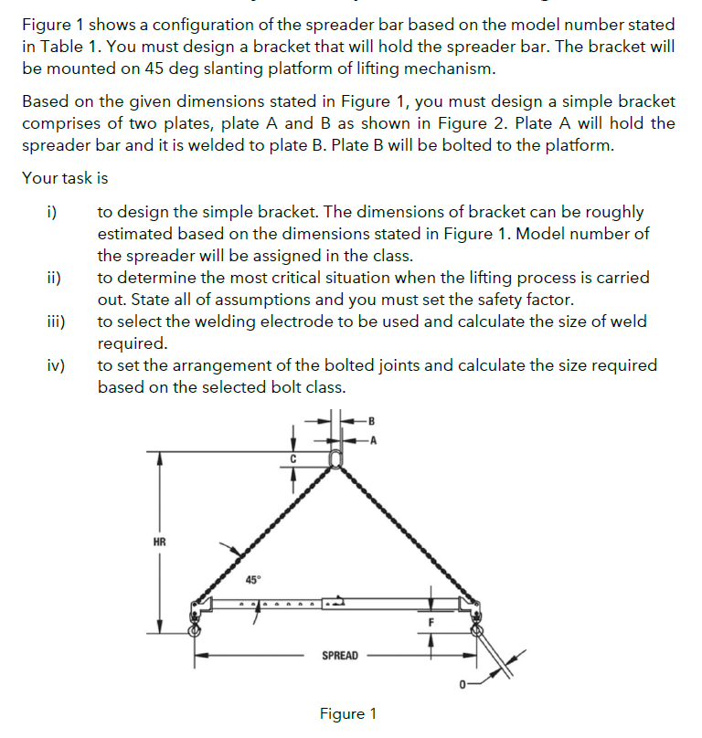
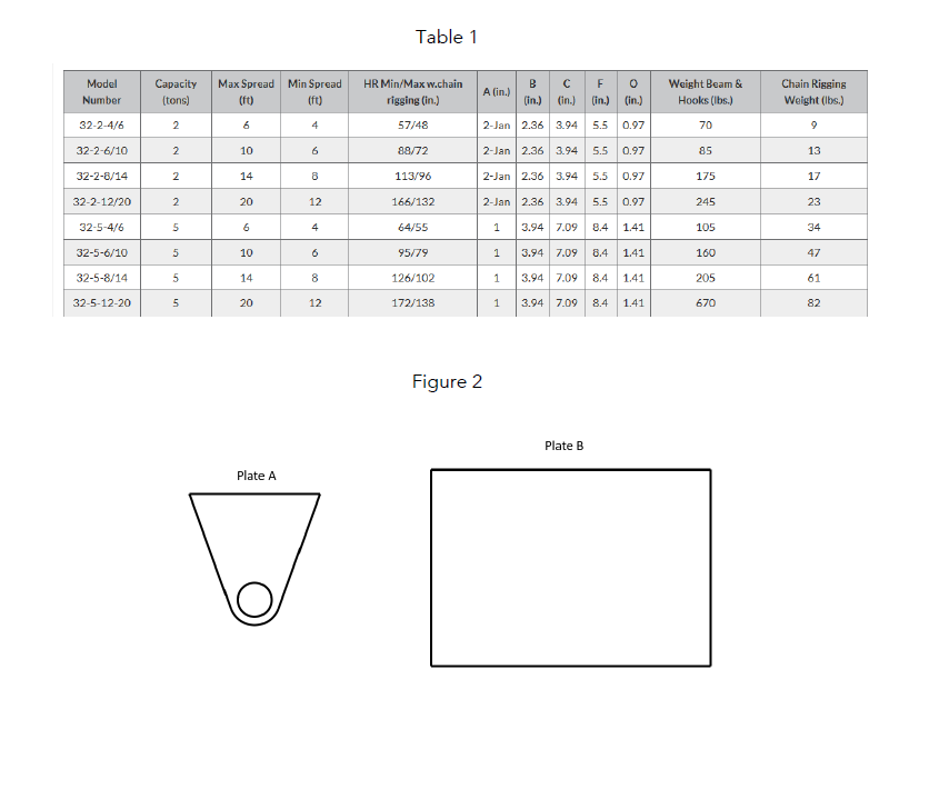
Figure 1 shows a configuration of the spreader bar based on the model number stated in Table 1. You must design a bracket that will hold the spreader bar. The bracket will be mounted on 45 deg slanting platform of lifting mechanism. Based on the given dimensions stated in Figure 1, you must design a simple bracket comprises of two plates, plate A and B as shown in Figure 2. Plate A will hold the spreader bar and it is welded to plate B. Plate B will be bolted to the platform. Your task is i) ii) iii) iv) to design the simple bracket. The dimensions of bracket can be roughly estimated based on the dimensions stated in Figure 1. Model number of the spreader will be assigned in the class. to determine the most critical situation when the lifting process is carried out. State all of assumptions and you must set the safety factor. to select the welding electrode to be used and calculate the size of weld required. to set the arrangement of the bolted joints and calculate the size required based on the selected bolt class. HR 45° C SPREAD Figure 1
Model Number 32-2-4/6 32-2-6/10 32-2-8/14 32-2-12/20 32-5-4/6 32-5-6/10 32-5-8/14 32-5-12-20 Capacity Max Spread (tons) (ft) 2 6 2 2 2 5 5 5 5 10 14 20 6 10 14 20 Min Spread (ft) 4 6 8 12 4 6 8 12 Plate A b Table 1 HR Min/Maxw.chain rigging (in.) 57/48 88/72 113/96 166/132 64/55 95/79 126/102 172/138 Figure 2 A (in.) B ? F (in.) (in.) (in.) (in.) EO 2-Jan 2.36 3.94 5.5 0.97 2-Jan 2.36 3.94 5.5 0.97 2-Jan 2.36 3.94 5.5 0.97 2-Jan 2.36 3.94 5.5 0.97 1 3.94 7.09 8.4 1.41 3.94 7.09 8.4 1.41 1 1 3.94 7.09 8.4 1.41 1 3.94 7.09 8.4 1.41 Plate B Weight Beam & Hooks (lbs.) 70 85 175 245 105 160 205 670 Chain Rigging Weight (lbs.) 9 13 17 23 34 47 61 82