Home /
Expert Answers /
Electrical Engineering /
figure-01-shows-the-circuit-diagram-of-a-buck-boost-converter-figure-01-i-sketch-the-waveform-of-pa186
(Solved): Figure 01 shows the circuit diagram of a buck-boost converter. Figure 01 I. Sketch the waveform of ...
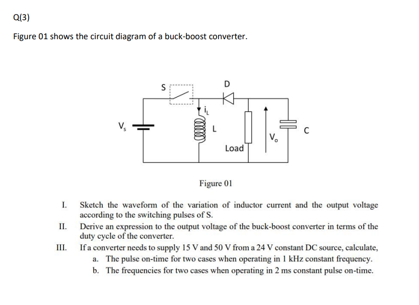
Figure 01 shows the circuit diagram of a buck-boost converter. Figure 01 I. Sketch the waveform of the variation of inductor current and the output voltage according to the switching pulses of \( \mathrm{S} \). II. Derive an expression to the output voltage of the buck-boost converter in terms of the duty cycle of the converter. III. If a converter needs to supply \( 15 \mathrm{~V} \) and \( 50 \mathrm{~V} \) from a \( 24 \mathrm{~V} \) constant DC source, calculate, a. The pulse on-time for two cases when operating in \( 1 \mathrm{kHz} \) constant frequency. b. The frequencies for two cases when operating in \( 2 \mathrm{~ms} \) constant pulse on-time.