Home /
Expert Answers /
Electrical Engineering /
fig-p5-15-5-16-for-the-circuit-shown-in-fig-p5-15-when-r-11-omega-l-1-mathrm-h-and-pa204
(Solved): Fig. P5.15 5.16 For the circuit shown in Fig. P5.15, when \( R=11 \Omega, L=1 \mathrm{H} \), and ...
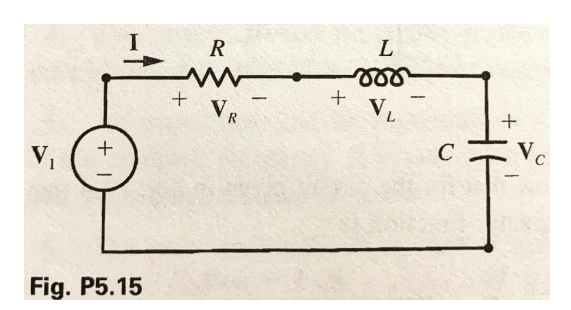
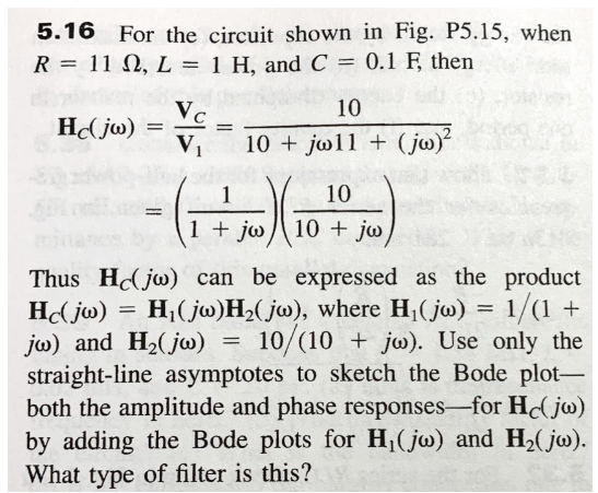
Fig. P5.15
5.16 For the circuit shown in Fig. P5.15, when \( R=11 \Omega, L=1 \mathrm{H} \), and \( C=0.1 \mathrm{~F} \), then \[ \begin{aligned} \mathbf{H}_{C}(j \omega) &=\frac{\mathbf{V}_{C}}{\mathbf{V}_{1}}=\frac{10}{10+j \omega 11+(j \omega)^{2}} \\ &=\left(\frac{1}{1+j \omega}\right)\left(\frac{10}{10+j \omega}\right) \end{aligned} \] Thus \( \mathbf{H}_{C}(j \omega) \) can be expressed as the product \( \mathbf{H}_{C}(j \omega)=\mathbf{H}_{1}(j \omega) \mathbf{H}_{2}(j \omega) \), where \( \mathbf{H}_{1}(j \omega)=1 /(1+ \) \( j \omega) \) and \( \mathbf{H}_{2}(j \omega)=10 /(10+j \omega) \). Use only the straight-line asymptotes to sketch the Bode plotboth the amplitude and phase responses-for \( \mathbf{H}_{C}(j \omega) \) by adding the Bode plots for \( \mathbf{H}_{1}(j \omega) \) and \( \mathbf{H}_{2}(j \omega) \). What type of filter is this?
Expert Answer
HC(j?)=H1(j?)H2(j?) ?? H1(j?)=11+j? this means there is a line with negative slope of 6 dB/octave in bB vs log(w) bode plot