Home /
Expert Answers /
Electrical Engineering /
fig-3-1-short-pulse-generator-fig-4-2-d-flip-flop-experiment-5-5-two-bit-counter-cascading-sim-pa751
(Solved): Fig. 3-1 Short pulse generator Fig. 4-2 D flip-flop Experiment 5.5: Two-bit counter Cascading sim ...
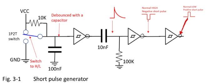
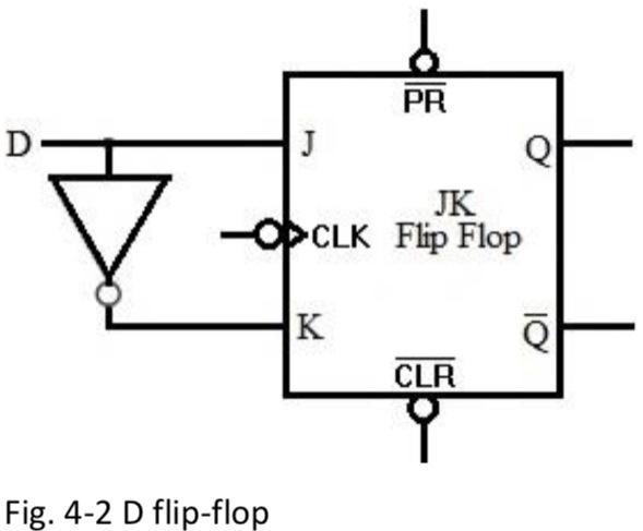
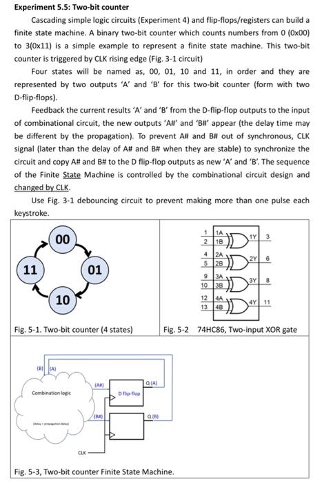
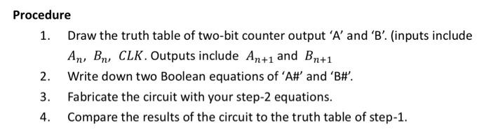
Fig. 3-1 Short pulse generator
Fig. 4-2 D flip-flop
Experiment 5.5: Two-bit counter Cascading simple logic circuits (Experiment 4) and flip-flops/registers can build a finite state machine. A binary two-bit counter which counts numbers from \( 0(0 \times 00) \) to \( 3(0 \times 11) \) is a simple example to represent a finite state machine. This two-bit counter is triggered by CLK rising edge (Fig. 3-1 circuit) Four states will be named as, 00, 01, 10 and 11 , in order and they are represented by two outputs ' \( A \) ' and ' \( B \) ' for this two-bit counter (form with two D-flip-flops). Feedback the current results ' \( A \) ' and ' \( B \) ' from the \( D \)-flip-flop outputs to the input of combinational circuit, the new outputs 'AH' and 'BH' appear (the delay time may be different by the propagation). To prevent \( A \# \) and \( B H \) out of synchronous, CLK signal (later than the delay of \( A \# \) and \( B \# \) when they are stable) to synchronize the circuit and copy A\# and BH to the D flip-flop outputs as new ' \( A \) ' and ' \( B \) '. The sequence of the Finite State Machine is controlled by the combinational circuit design and changed by CLK. Use Fig. 3-1 debouncing circuit to prevent making more than one pulse each keystroke. Fig. 5-1. Two-bit counter ( 4 states) Fig. 5-2 74HC86, Two-input XOR gate Fig. 5-3, Two-bit counter Finite State Machine.
Procedure 1. Draw the truth table of two-bit counter output ' \( A \) ' and ' \( B \) '. (inputs include \( A_{n}, B_{n}, C L K \). Outputs include \( A_{n+1} \) and \( B_{n+1} \) 2. Write down two Boolean equations of 'A\#' and 'B\#'. 3. Fabricate the circuit with your step-2 equations. 4. Compare the results of the circuit to the truth table of step-1.
Expert Answer
P.S: If you are having any doubt, please comment here, I will surely reply you.Please ask