Home /
Expert Answers /
Electrical Engineering /
drwa-the-connection-in-plc-and-drwa-the-ladder-diagram-part-2-threephasemotorin-pa895
(Solved): Drwa the connection in PLC and drwa the ladder diagram Part(2)Threephasemotorin ...
Drwa the connection in PLC and drwa the ladder diagram
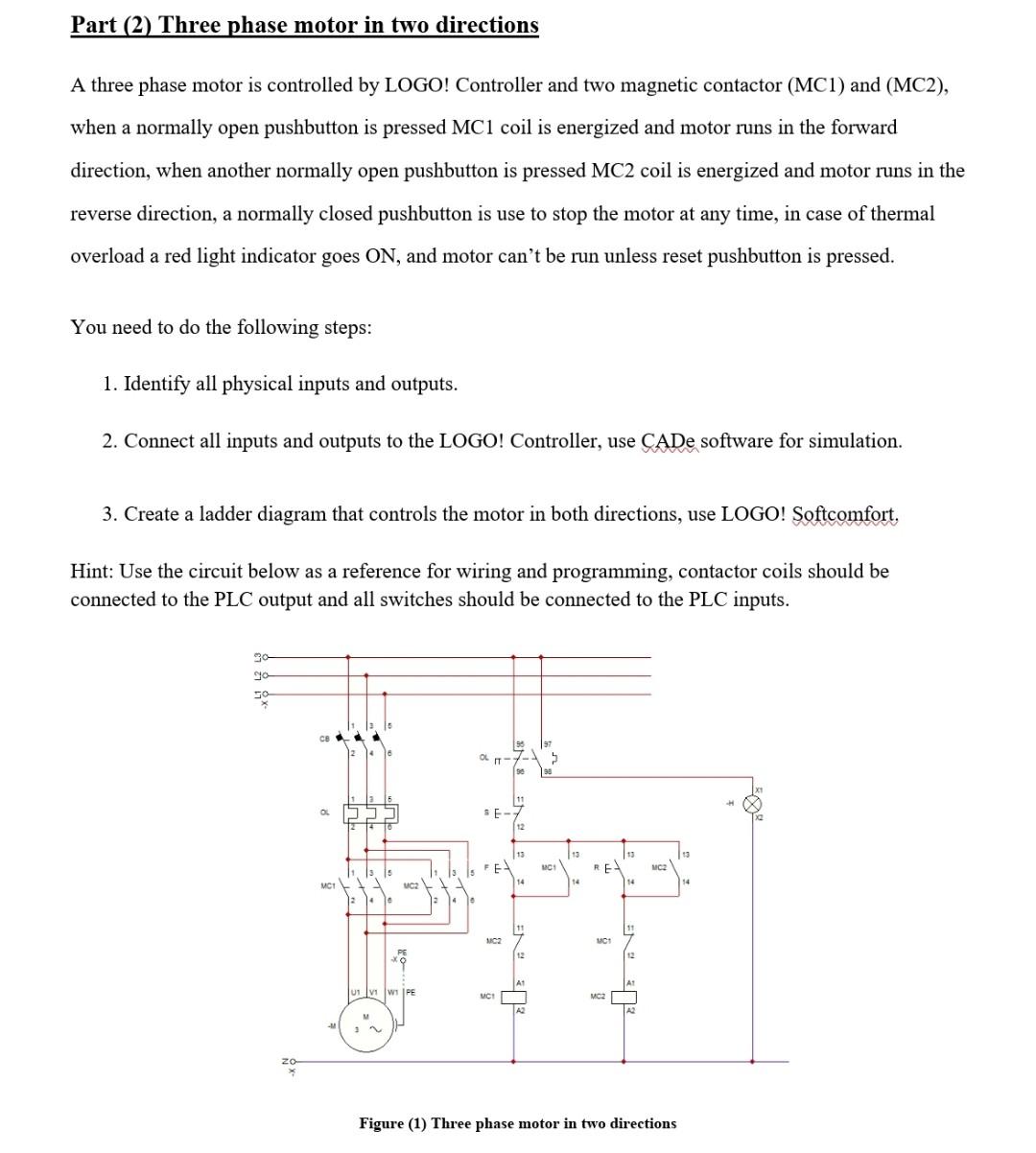
A three phase motor is controlled by LOGO! Controller and two magnetic contactor (MC1) and (MC2), when a normally open pushbutton is pressed MC1 coil is energized and motor runs in the forward direction, when another normally open pushbutton is pressed MC2 coil is energized and motor runs in the reverse direction, a normally closed pushbutton is use to stop the motor at any time, in case of thermal overload a red light indicator goes ON, and motor can't be run unless reset pushbutton is pressed. You need to do the following steps: 1. Identify all physical inputs and outputs. 2. Connect all inputs and outputs to the LOGO! Controller, use CADe software for simulation. 3. Create a ladder diagram that controls the motor in both directions, use LOGO! Softcomfort, Hint: Use the circuit below as a reference for wiring and programming, contactor coils should be connected to the PLC output and all switches should be connected to the PLC inputs. Figure (1) Three phase motor in two directions