Home /
Expert Answers /
Electrical Engineering /
draw-the-state-diagram-for-the-finite-state-machine-13-2-consider-the-sequential-logic-circuit-g-pa491
(Solved): draw the state diagram for the finite state machine 13. [2] Consider the sequential logic circuit g ...
draw the state diagram for the finite state machine
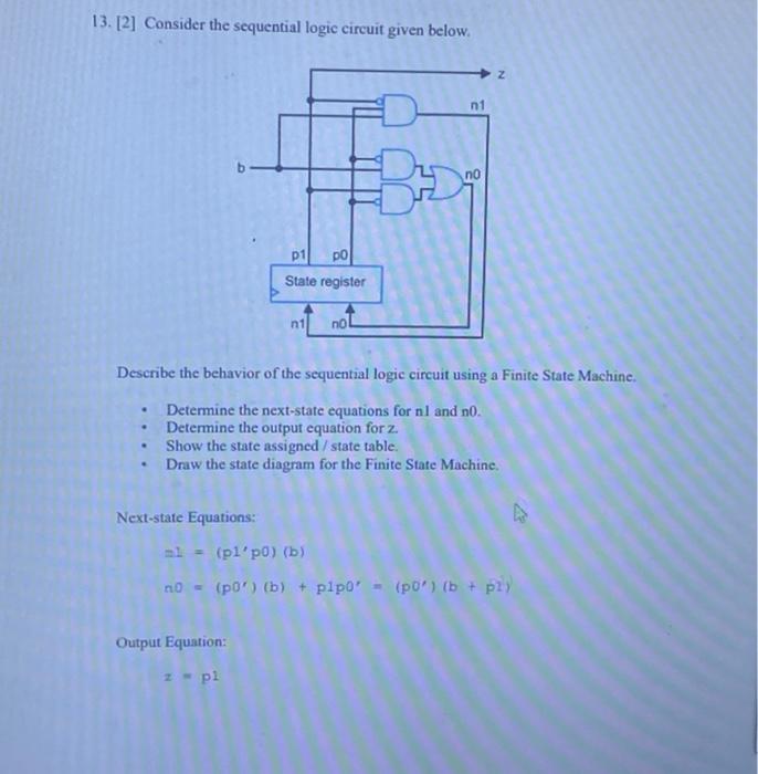
13. [2] Consider the sequential logic circuit given below. Describe the behavior of the sequential logic circuit using a Finite State Machine. - Determine the next-state equations for and no. - Determine the output equation for . - Show the state assigned/state table. - Draw the state diagram for the Finite State Machine. Next-state Equations: Output Equation: