Home /
Expert Answers /
Civil Engineering /
draw-the-shear-diagrams-for-members-ab-of-the-frame-follow-the-sign-convention-for-the-internal-loa-pa114
(Solved): Draw the shear diagrams for members AB of the frame. Follow the sign convention for the internal loa ...
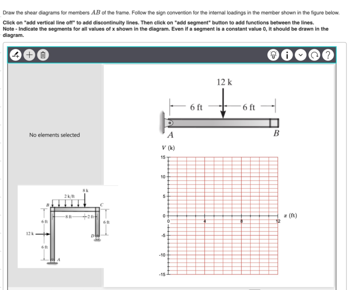
Draw the shear diagrams for members
ABof the frame. Follow the sign convention for the internal loadings in the member shown in the figure below. Click on "add vertical line off" to add discontinuity lines. Then click on "add segment" button to add functions between the lines. Note - Indicate the segments for all values of x shown in the diagram. Even if a segment is a constant value 0 , it should be drawn in the diagram. ? (B) i)
vvNo elements selected t)