Home /
Expert Answers /
Electrical Engineering /
draw-the-ladder-logic-diagram-for-the-process-below-when-there-is-someone-on-the-outer-pressure-pa680
(Solved): Draw the ladder logic diagram for the process below: - When there is someone on the outer pressure ...
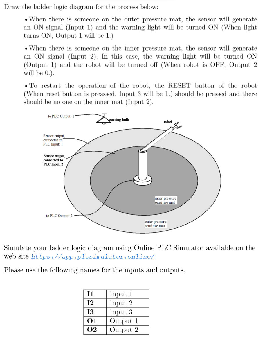
Draw the ladder logic diagram for the process below: - When there is someone on the outer pressure mat, the sensor will generate an ON signal (Input 1) and the warning light will be turned ON (When light turns \( \mathrm{ON} \), Output 1 will be 1 .) - When there is someone on the inner pressure mat, the sensor will generate an ON signal (Input 2). In this case, the warning light will be turned ON (Output 1) and the robot will be turned off (When robot is OFF, Output 2 will be 0 .). - To restart the operation of the robot, the RESET button of the robot (When reset button is presssed, Input 3 will be 1.) should be pressed and there should be no one on the inner mat (Input 2). Simulate your ladder logic diagram using Online PLC Simulator available on the web site https://app.plcsimulator.online/ Please use the following names for the inputs and outputs.