Home /
Expert Answers /
Electrical Engineering /
draw-the-ladder-logic-diagram-for-the-process-below-a-tank-is-used-to-mix-two-liquids-the-contro-pa947
(Solved): Draw the Ladder Logic Diagram for the process below: A tank is used to mix two liquids. The contro ...
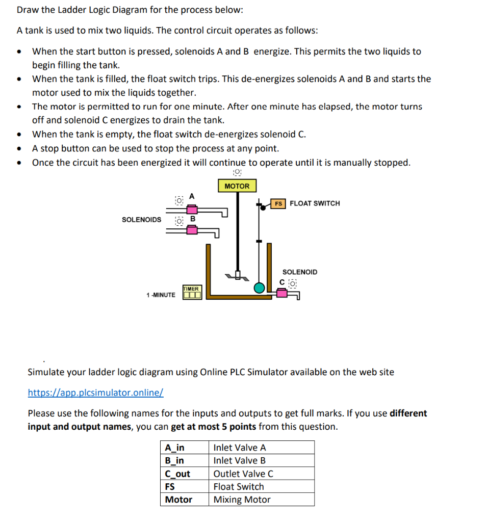
Draw the Ladder Logic Diagram for the process below: A tank is used to mix two liquids. The control circuit operates as follows: - When the start button is pressed, solenoids and energize. This permits the two liquids to begin filling the tank. - When the tank is filled, the float switch trips. This de-energizes solenoids A and B and starts the motor used to mix the liquids together. - The motor is permitted to run for one minute. After one minute has elapsed, the motor turns off and solenoid energizes to drain the tank. - When the tank is empty, the float switch de-energizes solenoid C. - A stop button can be used to stop the process at any point. - Once the circuit has been energized it will continue to operate until it is manually stopped. Simulate your ladder logic diagram using Online PLC Simulator available on the web site Please use the following names for the inputs and outputs to get full marks. If you use different input and output names, you can get at most 5 points from this question.
Expert Answer
steps for PLC ladder logic diagram simulation:• Before downloa
