Home /
Expert Answers /
Electrical Engineering /
draw-the-fsm-model-of-the-uart-transmitter-system-explained-below-based-on-the-flow-chart-nbsp-pa535
(Solved): Draw the FSM model of the UART transmitter system explained below (based on the flow chart) & ...
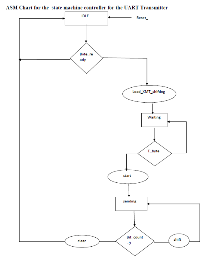
Draw the FSM model of the UART transmitter system explained below (based on the flow chart)
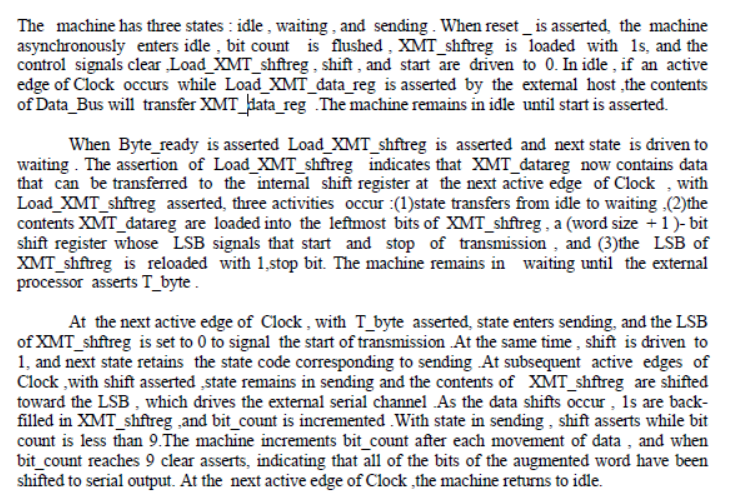
The machine has three states : idle, waiting, and sending. When reset is asserted, the machine asynchronously enters idle, bit count is flushed, XMT_shffreg is loaded with 1s, and the control signals clear,Load_XMT_shftreg, shift, and start are driven to 0 . In idle, if an active edge of Clock occurs while Load_XMT_data_reg is asserted by the external host,the contents of Data_Bus will transfer XMT_thata_reg .The machine remains in idle until start is asserted. When Byte_ready is asserted Load_XMT_shftreg is asserted and next state is driven to waiting. The assertion of Load_XMT_shftreg indicates that XMT_datareg now contains data that can be transferred to the internal shift register at the next active edge of Clock, with Load_XMT_shftreg asserted, three activities occur:(1)state transfers from idle to waiting,(2)the contents XMT_datareg are loaded into the leftmost bits of XMT_shffreg, a (word size + 1)-bit shift register whose LSB signals that start and stop of transmission, and (3)the LSB of XMT_shftreg is reloaded with 1,stop bit. The machine remains in waiting until the external processor asserts T_byte. At the next active edge of Clock, with T_byte asserted, state enters sending, and the LSB of XMT_shftreg is set to 0 to signal the start of transmission.At the same time, shift is driven to 1 , and next state retains the state code corresponding to sending .At subsequent active edges of Clock, with shift asserted,state remains in sending and the contents of XMT_shftreg are shifted toward the LSB , which drives the external serial channel .As the data shifts occur, 1s are backfilled in XMT_shftreg, and bit_count is incremented. With state in sending , shift asserts while bit count is less than 9. The machine increments bit_count after each movement of data, and when bit_count reaches 9 clear asserts, indicating that all of the bits of the augmented word have been shifted to serial output. At the next active edge of Clock, the machine returns to idle.
ASM Chart for the state machine controller for the UART Transmitter


