Home /
Expert Answers /
Electrical Engineering /
do-it-using-matlab-simulink-upload-circuits-and-simulations-as-images-single-phase-spwm-switching-pa574
(Solved): Do it using matlab/simulink. Upload circuits and simulations as images. Single phase SPWM switching ...
Do it using matlab/simulink. Upload circuits and simulations as images.
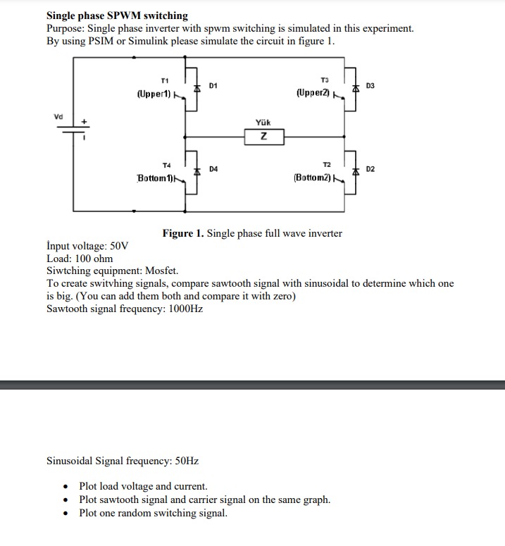
Single phase SPWM switching Purpose: Single phase inverter with spwm switching is simulated in this experiment. By using PSIM or Simulink please simulate the circuit in figure 1. Innut voltage: Figure 1. Single phase full wave inverter Load: Siwtching equipment: Mosfet. To create switvhing signals, compare sawtooth signal with sinusoidal to determine which one is big. (You can add them both and compare it with zero) Sawtooth signal frequency: Sinusoidal Signal frequency: - Plot load voltage and current. - Plot sawtooth signal and carrier signal on the same graph. - Plot one random switching signal.
Expert Answer
1. Load voltage plotting2. Load current plottingplease refer the above imageI HAVE DONE WITH SOME PARTS FROM THE ABOVE PROBLEM