Home /
Expert Answers /
Electrical Engineering /
design-a-ladder-logic-diagram-for-the-following-plc-system-decription-3-one-of-the-water-rides-at-a-pa876
(Solved): design a ladder logic diagram for the following PLC system decription 3. One of the water rides at a ...
design a ladder logic diagram for the following PLC system decription
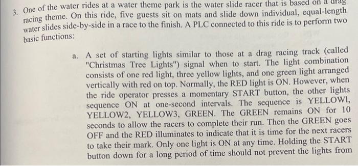
3. One of the water rides at a water theme park is the water slide racer that is based on a drag racing theme. On this ride, five guests sit on mats and slide down individual, equal-length water slides side-by-side in a race to the finish. A PLC connected to this ride is to perform two basic functions: a. A set of starting lights similar to those at a drag racing track (called "Christmas Tree Lights") signal when to start. The light combination consists of one red light, three yellow lights, and one green light arranged vertically with red on top. Normally, the RED light is ON. However, when the ride operator presses a momentary START button, the other lights sequence at one-second intervals. The sequence is YELLOWI, YELLOW2, YELLOW3, GREEN. The GREEN remains ON for 10 seconds to allow the racers to complete their run. Then the GREEN goes OFF and the RED illuminates to indicate that it is time for the next racers to take their mark. Only one light is ON at any time. Holding the START button down for a long period of time should not prevent the lights from
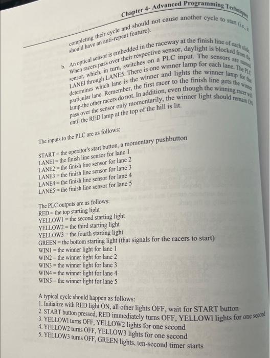
shotld have an anti-repeat feature). sensor, which, in turn, switches on a The winner lamp for each lane. The pey LANEl through LANE is the winner and lights the winner lamp for se lamp-the other racers do not. In addition, eventarily, the winner light should remain of pass over the sensor only the of the hill is lit. The inputs to the PLC are as follows: START = the operator's start button, a momentary pushbutton LANEI = the finish line sensor for lane 1 LANE2 the finish line sensor for lane 2 LANE3 3 the finish line sensor for lane 3 LANE4 = the finish line sensor for lane 4 LANE the finish line sensor for lane 5 The PLC outputs are as follows: RED the top starting light YELLOWI the second starting light YELLOW2 the third starting light YELLOW3 the fourth starting light GREEN = the bottom starting light (that signals for the racers to start) WIN the winner light for lane 1 WIN2 the winner light for lane 2 WIN 3 = the winner light for lane 3 WIN4 the winner light for lane 4 WIN the winner light for lane 5 A typical cycle should happen as follows: 1. Initialize with RED light ON, all other lights OFF, wait for START button 2. START button pressed, RED immediately turns OFF, YELLOWI lights for one seced 3. YELLOWI turns OFF, YELLOW2 lights for one second 4. YELLOW2 turn OFF, YELLOW3 lights for one second 5. YELLOW3 turns OFF, GREEN lights, ten-second timer starts
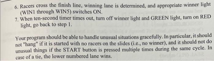
6. Racers cross the finish line, winning lane is determined, and appropriate winner light (WIN1 through WIN5) switches ON. 7. When ten-second timer times out, turn off winner light and GREEN light, turn on RED light, go back to step 1 . Your program should be able to handle unusual situations gracefully. In particular, it should not "hang" if it is started with no racers on the slides (i.e., no winner), and it should not do unusual things if the START button is pressed multiple times during the same cycle. In case of a tie, the lower numbered lane wins.