(Solved): Create an Ethernet SwitchThis activity configures the r1 VM as an Ethernet switch (aka. multi-port b ...
Create an Ethernet Switch
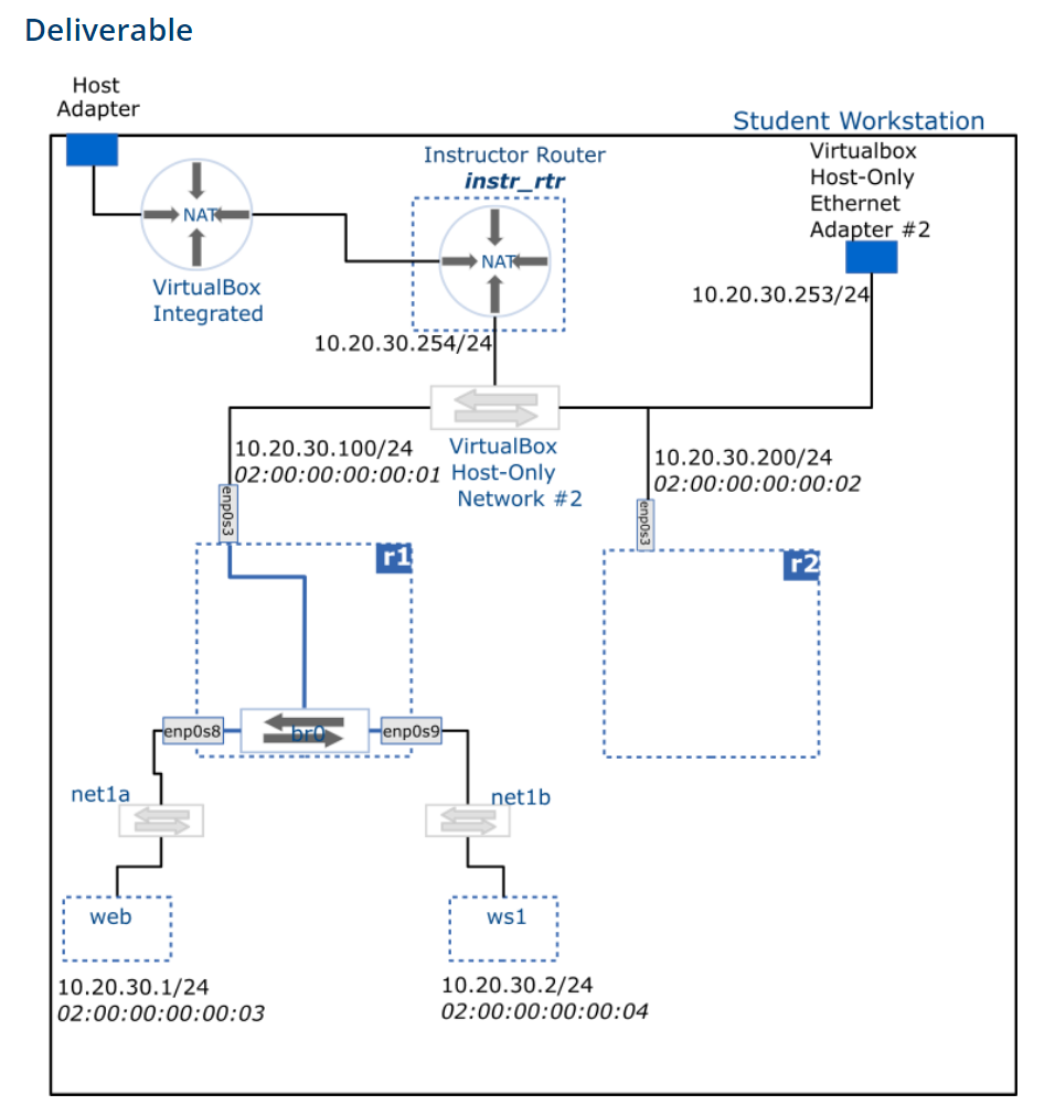
This activity configures the r1 VM as an Ethernet switch (aka. multi-port bridge) by adding additional Ethernet interfaces and creating a logical "Bridge" between them.
This 'switch' is placed in a network hierarchy and traffic is observed passing 'through' the switch.

- Ensure you have completed the Project Setup activity and that you can access r1 and r2 from the host.
- Configure two more Ethernet adapters on r1 as follows (power off the VM before applying the changes):
- Adapter 2: connected to an Internal Network: net1a
- Adapter 3: connected to an Internal Network: net1b
- These interfaces will use the Paravirtualized Network (virtio-net) Adapter Type and have Promiscuous Mode set to Allow All
These adapters will be named enp0s8 and enp0s9 respectively (see Red Hat interface naming conventions below)
Once we have configured the bridge, the two internal networks (net1a and net1b) together with the Host-Only network #2 will be joined into a single broadcast domain.
Clone a new VM named web (linked clone, reset MAC address) from the centos_8_base VM and configure its Network Adapter 1 as follows:
- Connected to Internal Networking – net1a network
- MAC address: 02:00:00:00:00:03
- Clone another VM named ws1 (workstation 1) as above and configure its Network Adapter 1 as follows:
- Connected to Internal Networking – net1b network
- MAC address: 02:00:00:00:00:04
- Start the web and ws1 VM’s and find out their IP addresses using the ip command.
- Ensure you are able to ping ws1 from web and vice versa. You should also be able to ping r1, r2 and the host from both web and ws1.
You will complete the following tasks using the nmtui tool.
- Delete any existing connections (aka configurations)
- Create a connection for the bridge br0
- Create a connections for each of the slave interfaces: enp0s3, enp0s8, enp0s9, adding them as ports to the br0
- Enable autoconnection of the slave interfaces on the bridge connection
- Reload the bridge configuration
- Set br0's IP via DHCP:
dhclient br0 –v(the -v option suppresses errors)
The IP address assigned to the br0 is used solely for administration of the machine, i.e. in order to connect r1 via SSH (for example, if we need to transfer files). A bridge doesn't require an IP Address to function as a bridge.
Ensure you are still able to observe traffic traversing the network.
If you would like to instead use the nmcli command to achieve the same result, the command incantations you would need are provided below. The nmcli command might be quicker at the cost of clarity.
Record the precise commands (ip link, ip address, bridge, nmtui navigation, nmcli connection) used to configure the individual interfaces, IP settings, and bridge configuration on the r1 VM. You will need this later in the course.
Discover and record the IP address of the default gateways for all VM's except the instr_rtr VM (they will need to be running)
Capture ping traffic from the web VM to 8.8.8.8 simultaneously at web, ws1 and r1 VM's on the enp0s3, using tcpdump
The following command will capture traffic going through enp0s3 and save it to a file named my_capture.pcap:
sudo tcpdump -i enp0s3 -w my_capture.pcap
Copy the capture files back to your host using sftp and view them using Wireshark.
Identify the source and destination MAC address (as given in the Ethernet frame) of the ping traffic on your r1, and web VM's.