Home /
Expert Answers /
Electrical Engineering /
counter-verilog-consider-the-circuit-in-figure-1-it-is-a-4-bit-synchronous-counter-which-uses-four-pa233
(Solved): counter verilog Consider the circuit in Figure 1. It is a 4-bit synchronous counter which uses four ...
counter verilog
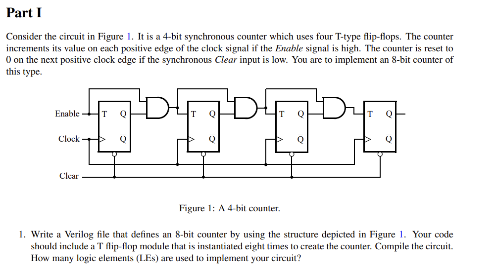
Consider the circuit in Figure 1. It is a 4-bit synchronous counter which uses four T-type flip-flops. The counter increments its value on each positive edge of the clock signal if the Enable signal is high. The counter is reset to 0 on the next positive clock edge if the synchronous Clear input is low. You are to implement an 8-bit counter of this type. Figure 1: A 4-bit counter. 1. Write a Verilog file that defines an 8-bit counter by using the structure depicted in Figure 1. Your code should include a flip-flop module that is instantiated eight times to create the counter. Compile the circuit. How many logic elements (LEs) are used to implement your circuit?
Expert Answer
An 8-bit counter using T-type flip-flops in VerilogThey are 4 steps to implement the 8- bit counter using in verilog.Step 1: Create a T-type flip-flop moduleStep 2: Create an 8-bit counter module Step 3: Compile the circuit Step 4: Count the logic elements (LEs) used