Home /
Expert Answers /
Electrical Engineering /
consider-the-single-line-diagram-of-the-power-system-shown-below-equipment-rating-are-given-below-pa674
(Solved): Consider the single line diagram of the power system shown below. Equipment rating are given below ...

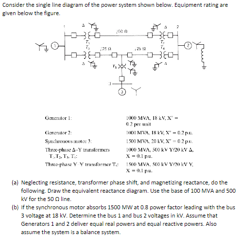
Consider the single line diagram of the power system shown below. Equipment rating are given below the figure. Generator 1: Generator 2: Synchronous motor 3 : Three-phase \\( \\Delta-Y \\) transformers \\( \\mathrm{T}_{1}, \\mathrm{~T}_{2}, \\mathrm{~T}_{3}, \\mathrm{~T}_{4} \\) : Three-phase \\( Y \\) \\( Y \\) transformer \\( T_{4} \\) : \\( 1000 \\mathrm{MV} \\Omega .18 \\mathrm{kV}, \\mathrm{X}^{v}= \\) 0.2 per unit IOCO MVA, I8 kV, \\( \\mathrm{X}^{\\mathrm{v}}=0.2 \\) p.e. \\( 1500 \\mathrm{MVA}, 20 \\mathrm{kV}, \\mathrm{X}=0.2 \\mathrm{pu} \\). \\( 1000 \\mathrm{MVA}, 500 \\mathrm{kV} \\mathrm{Y/20} \\mathrm{kV} \\Delta \\), \\( \\mathrm{X}=0.1 \\mathrm{pu} \\). \\( 1500 \\mathrm{MVA}, 500 \\mathrm{kV} \\) V/20 kV Y, \\( \\mathrm{x}=0.1 \\mathrm{pu} \\). (a) Neglecting resistance, transformer phase shift, and magnetizing reactance, do the following. Draw the equivalent reactance diagram. Use the base of \\( 100 \\mathrm{MVA} \\) and 500 \\( \\mathrm{kV} \\) for the \\( 50 \\Omega \\) line. (b) If the synchronous motor absorbs \\( 1500 \\mathrm{MW} \\) at 0.8 power factor leading with the bus 3 voltage at \\( 18 \\mathrm{kV} \\). Determine the bus 1 and bus 2 voltages in kV. Assume that Generators 1 and 2 deliver equal real powers and equal reactive powers. Also assume the system is a balance system.
Expert Answer
(a) The boost converter operates by storing energy in the inductor during the ON period (when the sw...