Home /
Expert Answers /
Electrical Engineering /
consider-the-following-rc-circuit-depicted-in-fig-1-and-derive-the-system-impulse-response-ma-pa994
(Solved): Consider the following RC circuit depicted in Fig. 1 and derive the system impulse response \( \ma ...
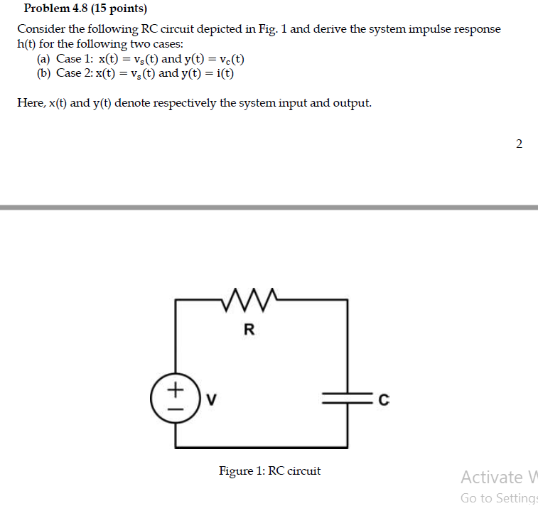
Consider the following RC circuit depicted in Fig. 1 and derive the system impulse response \( \mathrm{h}(\mathrm{t}) \) for the following two cases: (a) Case 1: \( \mathrm{x}(\mathrm{t})=\mathrm{v}_{\mathrm{s}}(\mathrm{t}) \) and \( \mathrm{y}(\mathrm{t})=\mathrm{v}_{\mathrm{c}}(\mathrm{t}) \) (b) Case \( 2: \mathrm{x}(\mathrm{t})=\mathrm{v}_{\mathrm{s}}(\mathrm{t}) \) and \( \mathrm{y}(\mathrm{t})=\mathrm{i}(\mathrm{t}) \) Here, \( x(t) \) and \( y(t) \) denote respectively the system input and output. Figure 1: RC circuit