Home /
Expert Answers /
Civil Engineering /
based-on-the-layout-of-the-water-supply-system-as-show-in-figure-1-flow-through-the-delivery-pip-pa567
(Solved): Based on the layout of the water supply system, as show in Figure 1, flow through the delivery pip ...
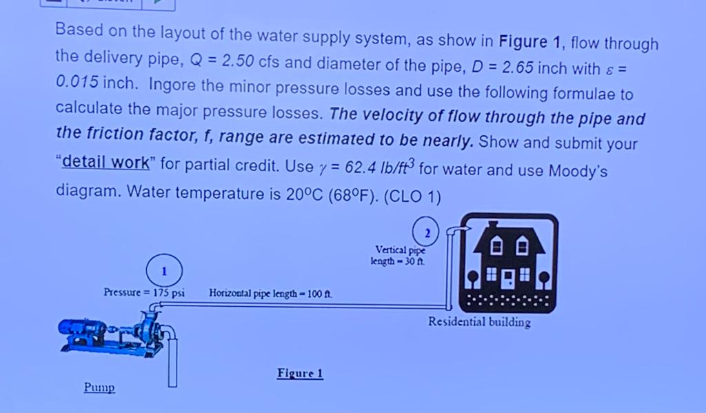
Based on the layout of the water supply system, as show in Figure 1, flow through the delivery pipe, Q = 2.50 cfs and diameter of the pipe, D = 2.65 inch with & = 0.015 inch. Ingore the minor pressure losses and use the following formulae to calculate the major pressure losses. The velocity of flow through the pipe and the friction factor, f, range are estimated to be nearly. Show and submit your "detail work" for partial credit. Use y = 62.4 lb/ft3 for water and use Moody's diagram. Water temperature is 20°C (68°F). (CLO 1) Pressure = 175 psi Pump Horizontal pipe length - 100 ft. Figure 1 Vertical pipe length-30 ft. 00 Residential building
Expert Answer
Ans) Apply Bernoulli equation between point 1 and 2 respectively, P1/ + V12/2g + Z1 = P2/ + V22/2g + Z2 + hL Pressure at point 1 = 175 psi or 25200 psf Velocity at point 1 = velocity at point 2 so velocity head will cancel out Let point 1 be datum so
