(Solved): b) The bode diagram of a dynamic system is shown in Figure 1.2. Using the asymptote approximation, ...
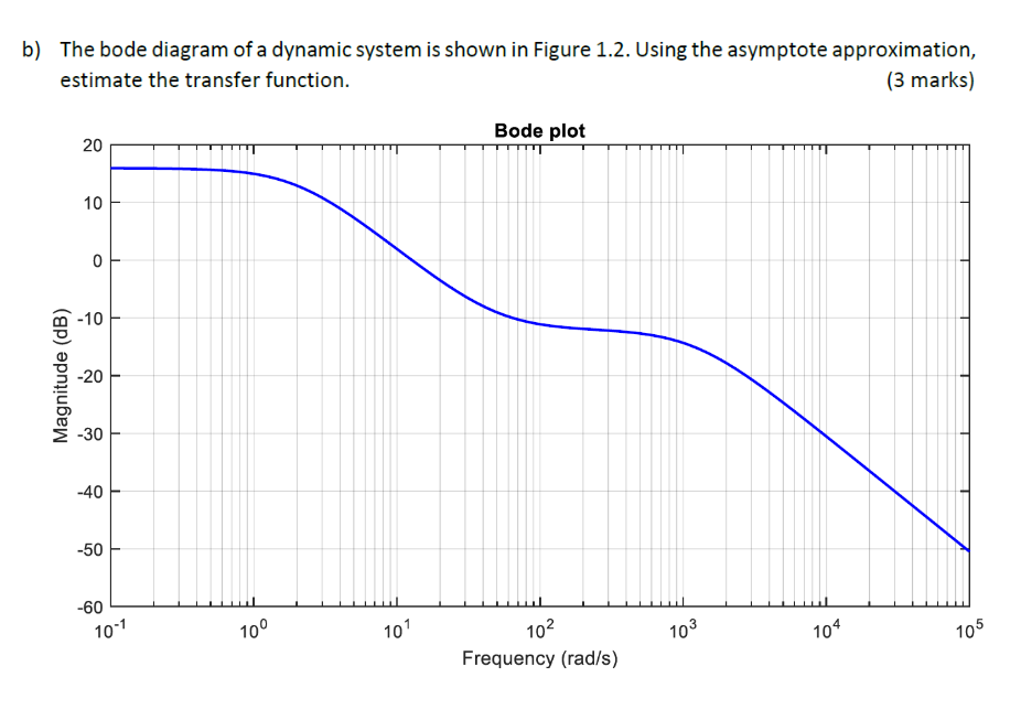
b) The bode diagram of a dynamic system is shown in Figure 1.2. Using the asymptote approximation, estimate the transfer function. Question 2 | ULO2 | 15 marks a) The Bode diagram of an unknown system
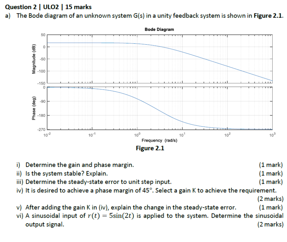
G(s)in a unity feedback system is shown in Figure 2.1. Bode Diagram Figure 2.1 i) Determine the gain and phase margin. ii) Is the system stable? Explain. iii) Determine the steady-state error to unit step input. iv) It is desired to achieve a phase margin of
45\deg . Select a gain
Kto achieve the requirement. v) After adding the gain
Kin (iv), explain the change in the steady-state error. vi) A sinusoidal input of
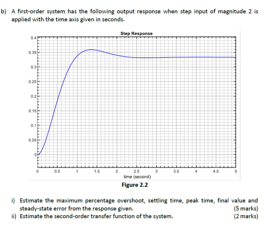
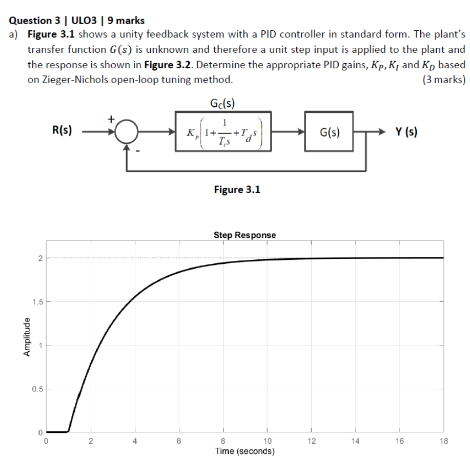
r(t)=5sin(2t)is applied to the system. Determine the sinusoidal output signal. b) A first-order system has the following output response when step input of magnitude 2 is applied with the time axis given in seconds. Step Response Figure 2.2 i) Estimate the maximum percentage overshoot, settling time, peak time, final value and steady-state error from the response given. ii) Estimate the second-order transfer function of the system. (2 marks) Question 3 | ULO3 | 9 marks a) Figure 3.1 shows a unity feedback system with a PID controller in standard form. The plant's transfer function
G(s)is unknown and therefore a unit step input is applied to the plant and the response is shown in Figure 3.2. Determine the appropriate PID gains,
K_(P),K_(I)and
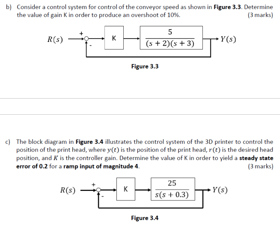
K_(D)based on Zieger-Nichols open-loop tuning method.b) Consider a control system for control of the conveyor speed as shown in Figure 3.3. Determine the value of gain
Kin order to produce an overshoot of
10%. c) The block diagram in Figure 3.4 illustrates the control system of the 3D printer to control the position of the print head, where
y(t)is the position of the print head,
r(t)is the desired head position, and
Kis the controller gain. Determine the value of
Kin order to yield a steady state error of 0.2 for a ramp input of magnitude 4 .