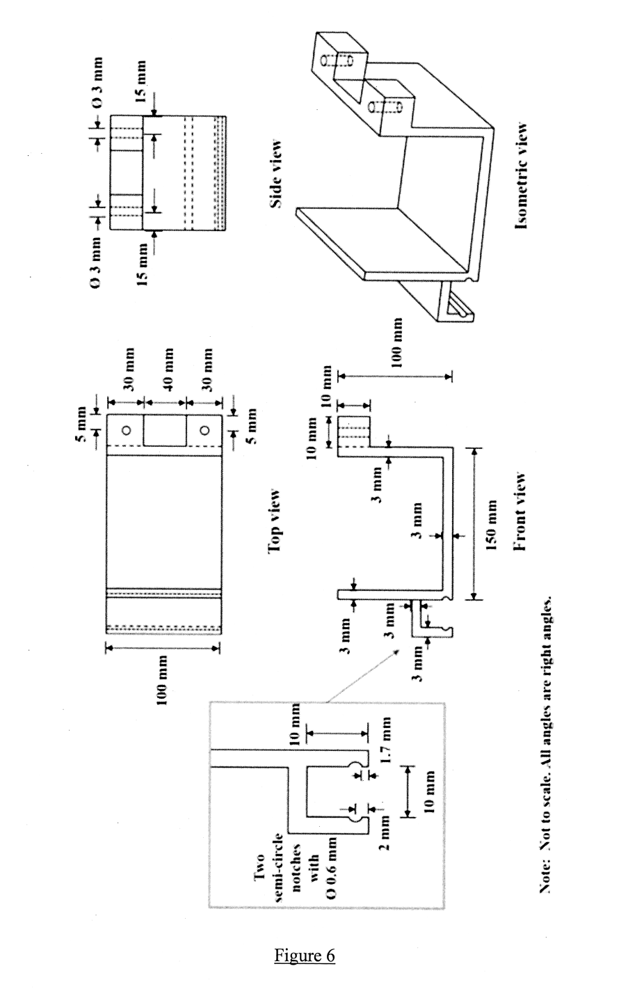
As an element of an assembly, the component shown in Figure 6 has been designedThe two 3 mm diameter holes are for anchoring of the component to an existingmachine. The U-shape channel is for the laying of cables, with notches at the sidewallA thin plastic plate of 0.5 mm thickness of the appropriate length (not shown andmanufactured separately) will be subsequently inserted to cover the U-channel toconceal the cables. The exact location and geometry of the U-shape channel are notcritical provided that the cables can be concealed.
The designer has chosen polycarbonate (PC), a thermal plastic, as the material for thecomponent. For prototype testing, 5 units are to be produced initially. However, it isexpected that to satisfy initial demand, 500,000 units of the component are required.and possibly many more for future demand.
The 5 units of the prototype are to be fabricated by 3D. If the prototype functions asexpected, the component is to be plastic injection moulded for mass production.


As an element of an assembly, the component shown in Figure 6 has been designed. The two 3 mm diameter holes are for anchoring of the component to an existing machine. The U-shape channel is for the laying of cables, with notches at the sidewall. A thin plastic plate of 0.5 mm thickness of the appropriate length (not shown and manufactured separately) will be subsequently inserted to cover the U-channel to conceal the cables. The exact location and geometry of the U-shape channel are not critical provided that the cables can be concealed. The designer has chosen polycarbonate (PC), a thermal plastic, as the material for the component. For prototype testing, 5 units are to be produced initially. However, it is expected that to satisfy initial demand, 500,000 units of the component are required, and possibly many more for future demand. The 5 units of the prototype are to be fabricated by 3D. If the prototype functions as expected, the component is to be plastic injection moulded for mass production. From the perspectives of cost of production and the suitability of the production technology, discuss and explain if the choices of the manufacturing processes are appropriate: (i) 3D printing for prototype. (3 marks) (ii) Plastic injection moulding for mass production. (3 marks) The production engineer complains that the component has not been designed properly for manufacturing by plastic injection moulding. The design has not been optimised to reduce the complexity and cost of production. You are to resolve the design and production difficulties and challenges. Specifically, you are to provide answers for the following: (i) State, with explanations, the design feature(s) that could not be produced or not optimised for manufacturing by plastic injection moulding. (9 marks) (ii) Taking into consideration the functionality requirements and the manufacturing process, suggest design change(s) to address the identified design feature(s) that could not be produced or not optimised for manufacturing in (i). Do state any necessary assumptions required, including the possibility of revising some dimensions and features of the design for manufacturing (i.e. assuming that some design parameters can still be revised). (10 marks)
Figure 6

