Home /
Expert Answers /
Electrical Engineering /
an-rtd-is-used-in-the-bridge-circuit-as-shown-in-figure-2-the-bridge-circuit-comprises-of-r-pa980
(Solved): An RTD is used in the bridge circuit as shown in Figure 2. The bridge circuit comprises of R = ...
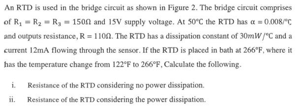
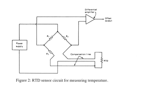
An RTD is used in the bridge circuit as shown in Figure 2. The bridge circuit comprises of R? = R? = R3 = 1500 and 15V supply voltage. At 50°C the RTD has ? = 0.008/°C and outputs resistance, R = 1100. The RTD has a dissipation constant of 30mW/°C and a current 12mA flowing through the sensor. If the RTD is placed in bath at 266°F, where it has the temperature change from 122°F to 266°F, Calculate the following. i. Resistance of the RTD considering no power dissipation. ii. Resistance of the RTD considering the power dissipation.
Power supply Differential amplifier Offset output Compensation lines 3 RTD Figure 2: RTD sensor circuit for measuring temperature.

