Home /
Expert Answers /
Electrical Engineering /
a-the-waveforms-given-in-figure-are-connected-to-the-latch-circuit-as-shown-assume-that-q-0-ini-pa345
(Solved): (a) The waveforms given in figure are connected to the latch circuit as shown. Assume that Q=0 ini ...
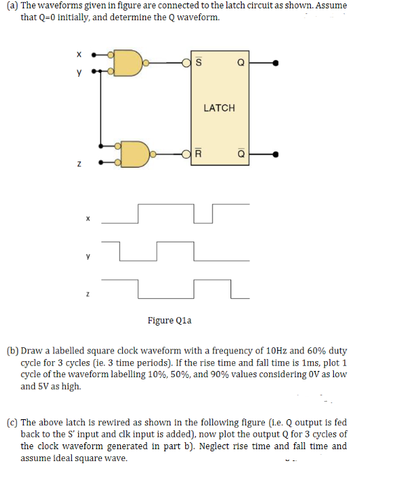
(a) The waveforms given in figure are connected to the latch circuit as shown. Assume that Q=0 initially, and determine the Q waveform. X S Y Z OR LATCH Q Z Figure Q1a (b) Draw a labelled square clock waveform with a frequency of 10Hz and 60% duty cycle for 3 cycles (ie. 3 time periods). If the rise time and fall time is 1ms, plot 1 cycle of the waveform labelling 10%, 50%, and 90% values considering OV as low and 5V as high. (c) The above latch is rewired as shown in the following figure (i.e. Q output is fed back to the S' input and clk input is added), now plot the output Q for 3 cycles of the clock waveform generated in part b). Neglect rise time and fall time and assume ideal square wave.
