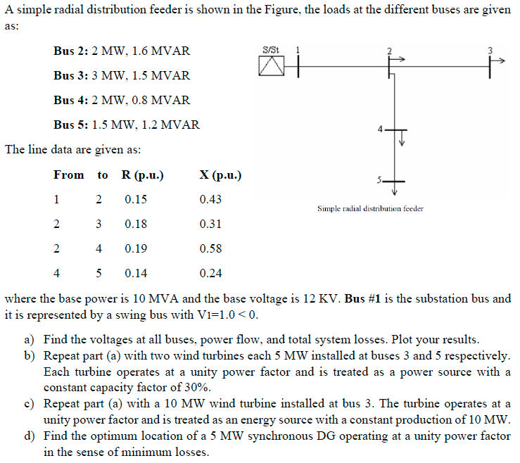
(Solved): A simple radial distribution feeder is shown in the Figure, the loads at the different buses are gi ...
A simple radial distribution feeder is shown in the Figure, the loads at the different buses are given as:
?Bus 2: 2 MW, 1.6 MVAR Bus 3:
3MW,1.5MVARBus 4: 2 MW, 0.8 MVAR Bus 5: 1.5 MW, 1.2 MVAR The line data are given as: Simple radial distribution feeder where the base power is 10 MVA and the base voltage is 12 KV . Bus #1 is the substation bus and it is represented by a swing bus with
V_(1)=1.0<0. a) Find the voltages at all buses, power flow, and total system losses. Plot your results. b) Repeat part (a) with two wind turbines each 5 MW installed at buses 3 and 5 respectively. Each turbine operates at a unity power factor and is treated as a power source with a constant capacity factor of
30%. c) Repeat part (a) with a 10 MW wind turbine installed at bus 3 . The turbine operates at a unity power factor and is treated as an energy source with a constant production of 10 MW . d) Find the optimum location of a 5 MW synchronous DG operating at a unity power factor in the sense of minimum losses.
