Home /
Expert Answers /
Electrical Engineering /
a-plc-ladder-diagram-with-its-input-and-output-address-assignment-is-shown-below-the-inputs-of-th-pa720
(Solved): A PLC ladder diagram with its input and output address assignment is shown below. The inputs of th ...
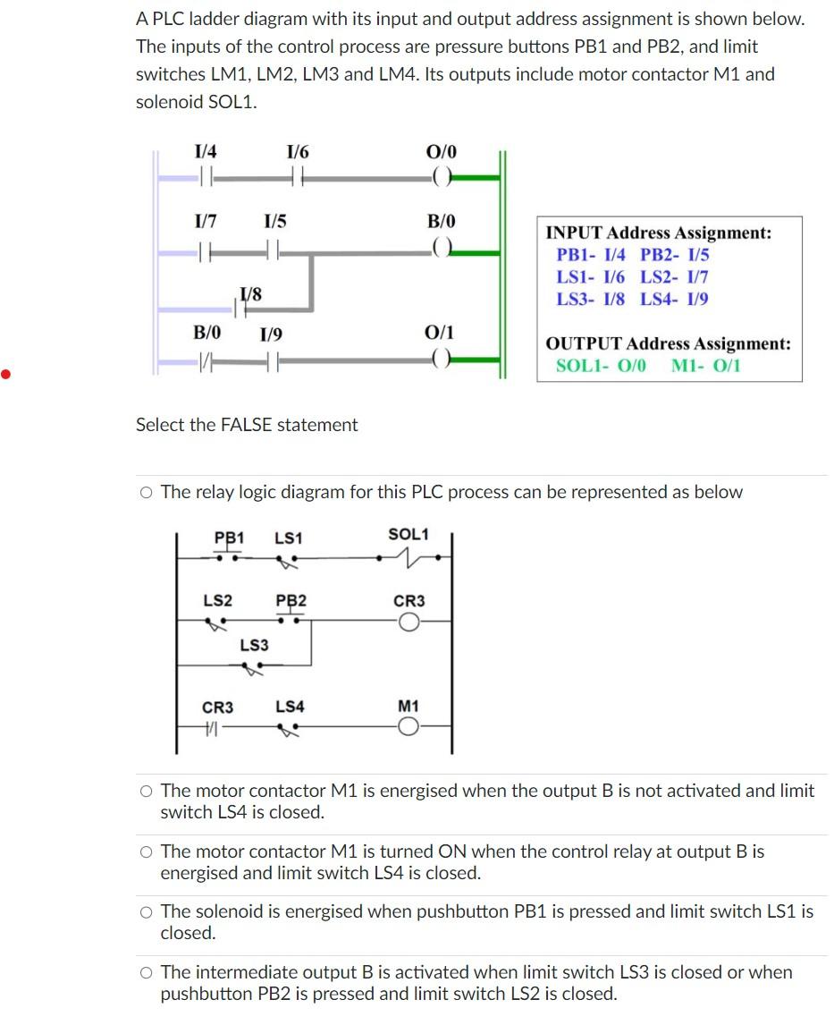
A PLC ladder diagram with its input and output address assignment is shown below. The inputs of the control process are pressure buttons PB1 and PB2, and limit switches LM1, LM2, LM3 and LM4. Its outputs include motor contactor \( \mathrm{M} 1 \) and solenoid SOL1. Select the FALSE statement The relay logic diagram for this PLC process can be represented as below The motor contactor \( \mathrm{M} 1 \) is energised when the output \( B \) is not activated and limit switch LS4 is closed. The motor contactor \( \mathrm{M} 1 \) is turned \( \mathrm{ON} \) when the control relay at output \( \mathrm{B} \) is energised and limit switch LS4 is closed. The solenoid is energised when pushbutton PB1 is pressed and limit switch LS1 is closed. The intermediate output B is activated when limit switch LS3 is closed or when pushbutton PB2 is pressed and limit switch LS2 is closed.
Expert Answer
For a given ladder diagram there is a relay logic diagram,