Home /
Expert Answers /
Mechanical Engineering /
a-gear-reduction-unit-uses-the-countershaft-shown-in-the-figure-gear-a-receives-power-from-anothe-pa600
(Solved): A gear reduction unit uses the countershaft shown in the figure. Gear A receives power from anothe ...
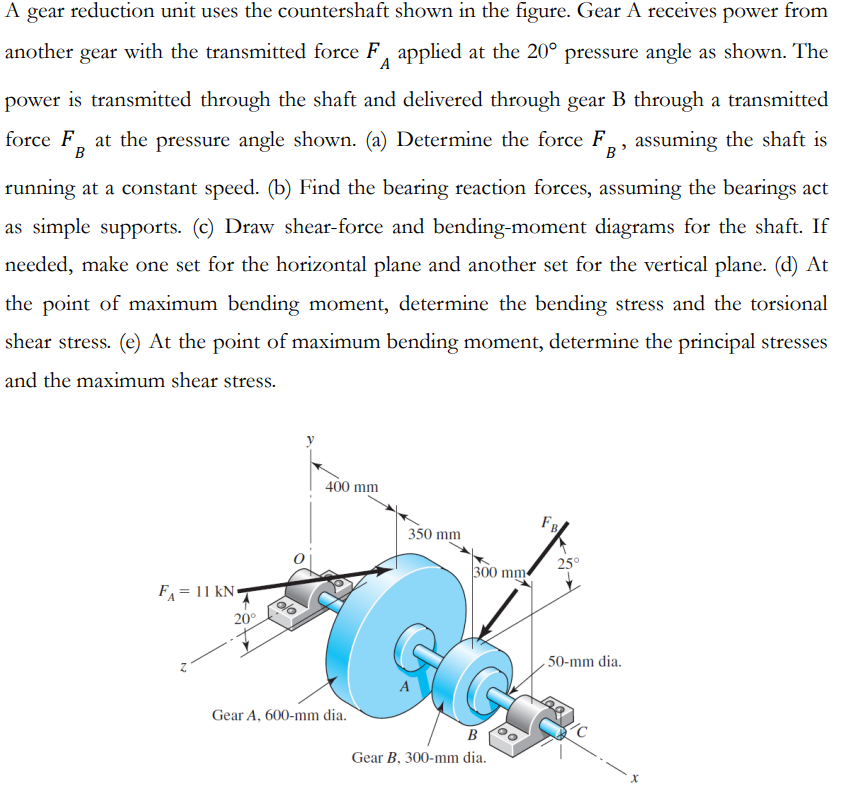
A gear reduction unit uses the countershaft shown in the figure. Gear A receives power from another gear with the transmitted force F applied at the 20° pressure angle as shown. The power is transmitted through the shaft and delivered through gear B through a transmitted force F at the pressure angle shown. (a) Determine the force F, assuming the shaft is ? running at a constant speed. (b) Find the bearing reaction forces, assuming the bearings act as simple supports. (c) Draw shear-force and bending-moment diagrams for the shaft. If needed, make one set for the horizontal plane and another set for the vertical plane. (d) At the point of maximum bending moment, determine the bending stress and the torsional shear stress. (e) At the point of maximum bending moment, determine the principal stresses and the maximum shear stress. FA=1 = 11 kN 20° 400 mm Gear A, 600-mm dia. 350 mm A 300 mm B Gear B, 300-mm dia. FB 25° 50-mm dia.