Home /
Expert Answers /
Mechanical Engineering /
a-basic-gas-turbine-system-is-illustrated-in-figure-q-4-below-figure-q4-basic-gas-turbine-pa756
(Solved): A basic gas turbine system is illustrated in Figure \\( Q 4 \\) below. Figure Q4 Basic gas turbine ...
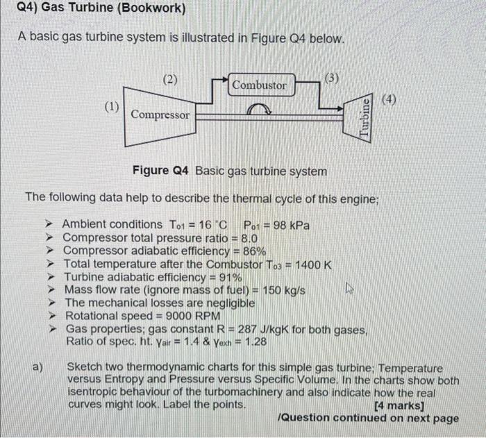
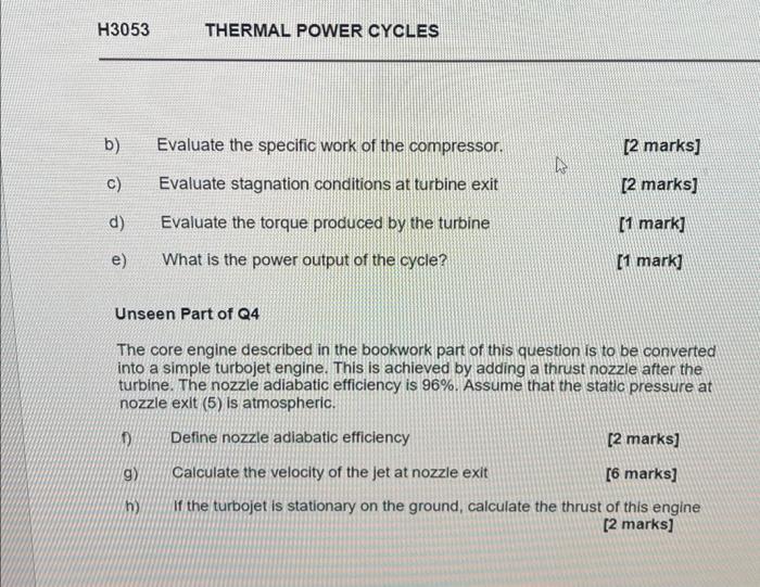
A basic gas turbine system is illustrated in Figure \\( Q 4 \\) below. Figure Q4 Basic gas turbine system The following data help to describe the thermal cycle of this engine; \\( > \\) Ambient conditions \\( \\mathrm{T}_{01}=16^{\\circ} \\mathrm{C} \\quad \\mathrm{P}_{01}=98 \\mathrm{kPa} \\) \\( > \\) Compressor total pressure ratio \\( =8.0 \\) > Compressor adiabatic efficiency \ > Total temperature after the Combustor \\( T_{03}=1400 \\mathrm{~K} \\) Turbine adiabatic efficiency \ > Mass flow rate (ignore mass of fuel) \\( =150 \\mathrm{~kg} / \\mathrm{s} \\) > The mechanical losses are negligible > Rotational speed \\( =9000 \\) RPM > Gas properties; gas constant R \\( =287 \\mathrm{~J} / \\mathrm{kgK} \\) for both gases, Ratio of spec. ht. Yair \\( =1.4 \\& \\) Yexh \\( =1.28 \\) a) Sketch two thermodynamic charts for this simple gas turbine; Temperature versus Entropy and Pressure versus Specific Volume. In the charts show both isentropic behaviour of the turbomachinery and also indicate how the real curves might look. Label the points. [4 marks] /Question continued on next page\r\nUnseen Part of Q4 The core engine described in the bookwork part of this question is to be converted into a simple turbojet engine. This is achieved by adding a thrust nozzle after the turbine. The nozzle adiabatic efficiency is \. Assume that the static pressure at nozzle exit (5) is atmospheric. f) Define nozzle adiabatic efficiency [2 marks] g) Calculate the velocity of the jet at nozzle exit [6 marks] h) If the turbojet is stationary on the ground, calculate the thrust of this engine [2 marks]