Home /
Expert Answers /
Mechanical Engineering /
6-the-pin-jointed-truss-frame-as-shown-in-the-figure-is-supported-by-smooth-rollers-at-b-and-hin-pa766
(Solved): 6. The pin-jointed truss frame as shown in the figure, is supported by smooth rollers at B and hin ...
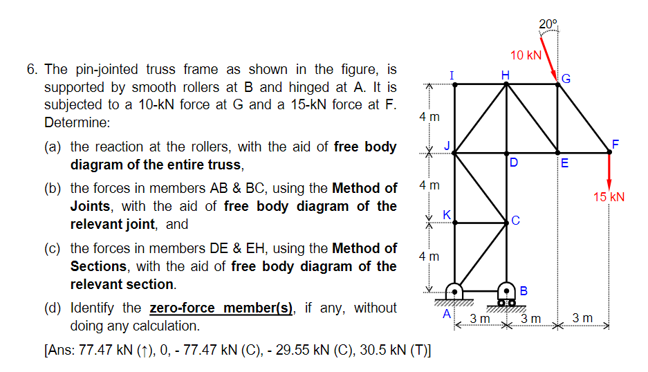
6. The pin-jointed truss frame as shown in the figure, is supported by smooth rollers at B and hinged at A. It is subjected to a 10-kN force at G and a 15-kN force at F. Determine: (a) the reaction at the rollers, with the aid of free body diagram of the entire truss, (b) the forces in members AB & BC, using the Method of Joints, with the aid of free body diagram of the relevant joint, and (c) the forces in members DE & EH, using the Method of Sections, with the aid of free body diagram of the relevant section. (d) Identify the zero-force member(s), if any, without doing any calculation. A [Ans: 77.47 kN (?), 0, - 77.47 kN (C), - 29.55 kN (C), 30.5 kN (T)] 4 m X 4 m 4 m I K 3 m 10 KN H 20° ? B 3 m G E F 15 KN 3 m