Home /
Expert Answers /
Electrical Engineering /
30-points-the-practical-silicon-si-diode-shown-in-figure-3-a-can-be-modeled-by-an-ideal-diode-pa377
(Solved): (30 points) The practical silicon (Si) diode shown in Figure 3(a) can be modeled by an ideal diode ...
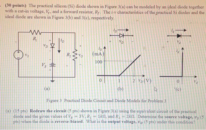

(30 points) The practical silicon (Si) diode shown in Figure 3(a) can be modeled by an ideal diode together with a cut-in voltage, , and a forward resistor, . The characteristics of the practical Si diodes and the ideal diode are shown in Figure 3(b) and 3(c), respectively. (a) (b) Figure 3 Practical Diode Circuit and Diode Models for Problem 3 (a) (15 pts) Redraw the circuit (5 pts) shown in Figure 3(a) using the equivalent circuit of the practical diode and the given values of , and . Determine the source voltage, pts) when the diode is reverse-biased. What is the output voltage, under this condition?
(b) (15 pts) Repeat Part (a) when the diode is forward-biased.