Home /
Expert Answers /
Electrical Engineering /
3-the-input-to-the-circuit-shown-in-figure-is-the-voltage-source-voltage-vs-the-output-is-the-pa808
(Solved): 3. The input to the circuit shown in figure is the voltage source voltage, vs. The output is the ...
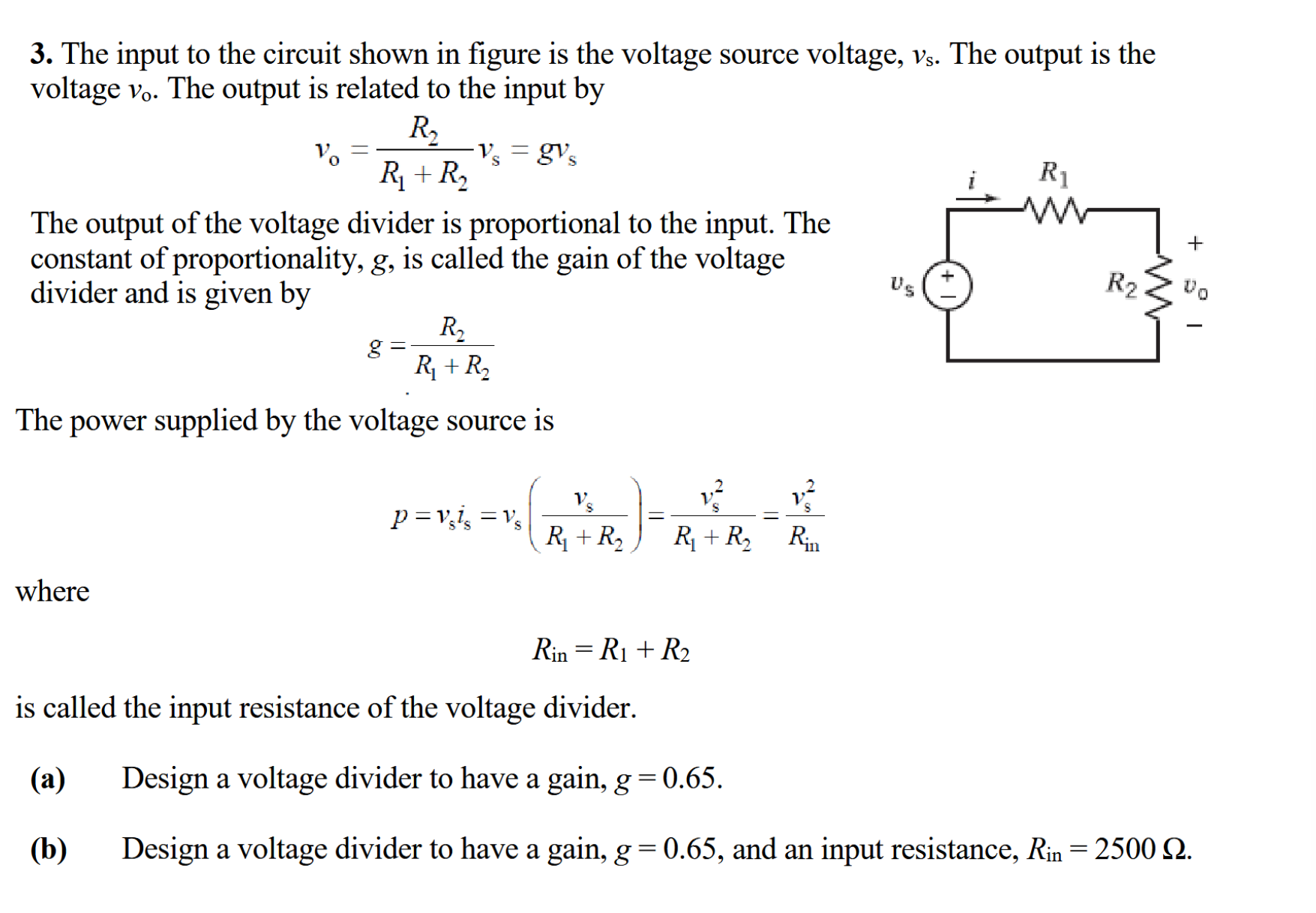
3. The input to the circuit shown in figure is the voltage source voltage, . The output is the voltage . The output is related to the input by The output of the voltage divider is proportional to the input. The constant of proportionality, , is called the gain of the voltage divider and is given by The power supplied by the voltage source is where is called the input resistance of the voltage divider. (a) Design a voltage divider to have a gain, . (b) Design a voltage divider to have a gain, , and an input resistance, .