Home /
Expert Answers /
Computer Science /
3-how-do-we-realize-2-times-4-decoder-with-logic-gates-use-the-truth-table-in-figure-3-pa337
(Solved): 3. How do we realize \( 2 \times 4 \) decoder with logic gates? Use the truth table in Figure \( 3. ...
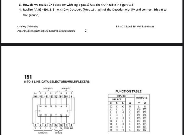
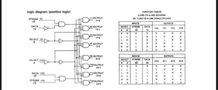
3. How do we realize \( 2 \times 4 \) decoder with logic gates? Use the truth table in Figure \( 3.3 \). 4. Realize \( f(A, B)=\Sigma(0,2,3) \) with \( 2 \times 4 \) Decoder. (Feed 16 th pin of the Decoder with \( 5 \mathrm{~V} \) and connect 8th pin to the ground). Altinbas University EE242 Digital Systems Laboratory Departmant of Electrical and Electronics Engineering \( \quad 2 \) 151 8-TO-1 LINE DATA SELECTORSMMULTIPLEXERS FUNCTION TARLE
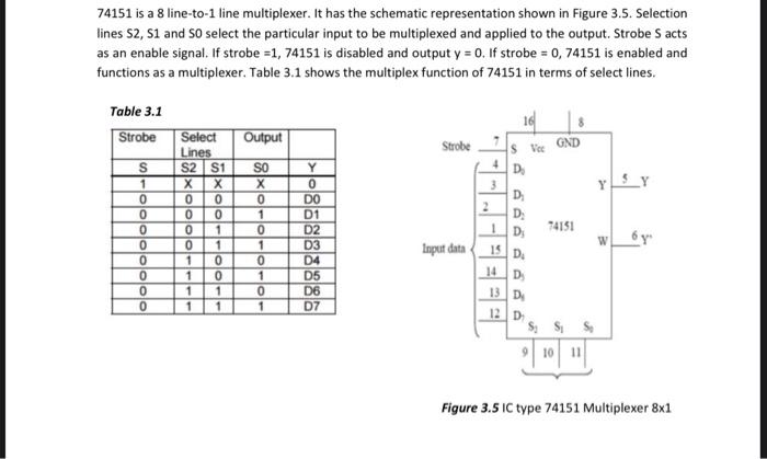
74151 is a 8 line-to-1 line multiplexer. It has the schematic representation shown in Figure 3.5. Selection lines \( \mathrm{S} 2, \mathrm{~S} 1 \) and \( \mathrm{S} 0 \) select the particular input to be multiplexed and applied to the output. Strobe \( \mathrm{S} \) acts as an enable signal. If strobe \( =1,74151 \) is disabled and output \( y=0 \). If strobe \( =0,74151 \) is enabled and functions as a multiplexer. Table \( 3.1 \) shows the multiplex function of 74151 in terms of select lines. Table \( 3.1 \) Figure 3.5 IC type 74151 Multiplexer \( 8 \times 1 \)
Runctiow TaButs 24ist-To-4uat btcooth On subt-10 - trat brevtlifiext
Expert Answer
1) Multiplexer is a combinational circuit that has maximum of 2" data inputs, 'n' selection li