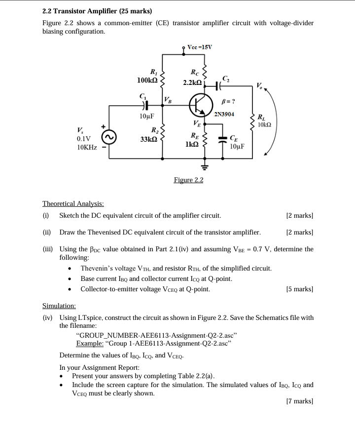
(Solved): 2.2 Transistor Amplifier (25 marks) Figure 2.2 shows a common-emitter (CE) transistor amplifier circ ...
2.2 Transistor Amplifier (25 marks) Figure 2.2 shows a common-emitter (CE) transistor amplifier circuit with voltage-divider biasing configuration. Theoretical Analysis: (i) Sketch the DC equivalent circuit of the amplifier circuit. (ii) Draw the Thevenised DC equivalent circuit of the transistor amplifier. (iii) Using the \beta _(DC) value obtained in Part 2.1 (iv) and assuming V_(BE)=0.7V, determine the following: Thevenin's voltage V_(TH), and resistor R_(TH), of the simplified circuit. Base current I_(BQ) and collector current I_(CQ) at Q -point. Collector-to-emitter voltage V_(CEQ ) at Q -point. Simulation: (iv) Using LTspice, construct the circuit as shown in Figure 2.2. Save the Schematics file with the filename: "GROUP_(N)UMBER-AEE6113-Assignment-Q2-2.asc" Example: "Group 1-AEE6113-Assignment-Q2-2.asc" Determine the values of I_(BQ),I_(CQ), and V_(CEQ). In your Assignment Report: Present your answers by completing Table 2.2(a). Include the screen capture for the simulation. The simulated values of I_(BQ),I_(CQ) and VCEQ must be clearly shown.