Home /
Expert Answers /
Mechanical Engineering /
1-theory-the-fundamentals-1-1-gear-ratio-compute-the-gear-ratio-for-the-following-system-figure-pa760
(Solved): 1 Theory: The fundamentals 1.1 Gear ratio Compute the gear ratio for the following system Figure ...
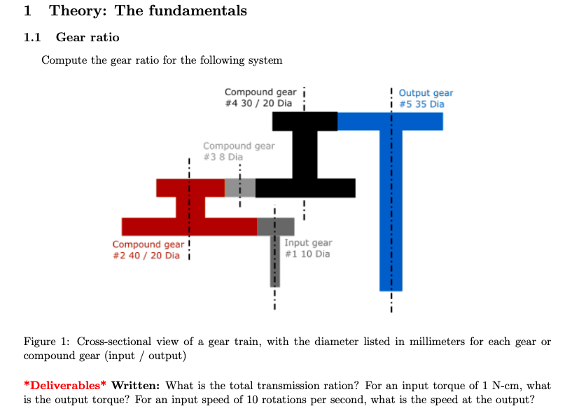

1 Theory: The fundamentals 1.1 Gear ratio Compute the gear ratio for the following system Figure 1: Cross-sectional view of a gear train, with the diameter listed in millimeters for each gear or compound gear (input / output) *Deliverables* Written: What is the total transmission ration? For an input torque of -cm, what is the output torque? For an input speed of 10 rotations per second, what is the speed at the output?
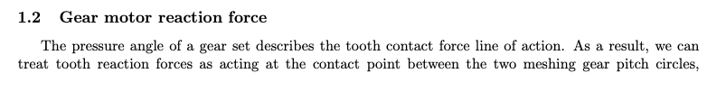
1.2 Gear motor reaction force The pressure angle of a gear set describes the tooth contact force line of action. As a result, we can treat tooth reaction forces as acting at the contact point between the two meshing gear pitch circles,
independent of real tooth orientation. This is a consequence of using a conjugate gear-tooth shape design. In the following system, the gears have a pressure angle of . The gears with 10 teeth are in diameter and the gears with 20 teeth are in diameter. Figure 2: Gear train with teeth listed for each gear *Deliverables* Written: For an input torque of in the clockwise (CW) direction. What are the forces acting at the teeth of the compound gear at points 1 and 2, represented in the righthanded frame shown in the image?
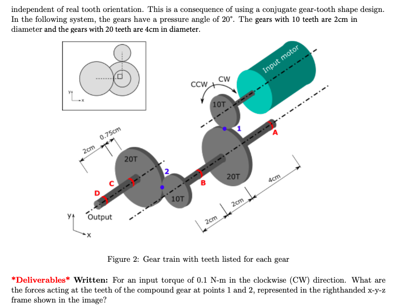
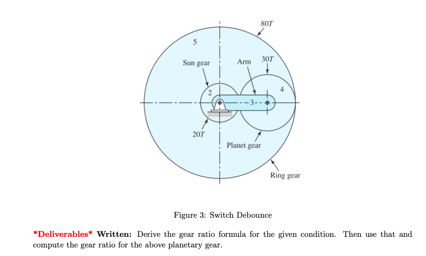
1.3 Planetary gear Shown below is the schematic of a planetary gearbox. The ring gear is held fixed. The input is the sun gear and the output is the planet carrier.
Figure 3: Switch Debounce *Deliverables* Written: Derive the gear ratio formula for the given condition. Then use that and compute the gear ratio for the above planetary gear.
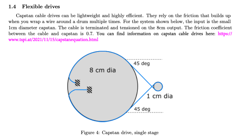
1.4 Flexible drives Capstan cable drives can be lightweight and highly efficient. They rely on the friction that builds up when you wrap a wire around a drum multiple times. For the system shown below, the input is the small diameter capstan. The cable is terminated and tensioned on the output. The friction coefficient between the cable and capstan is 0.7. You can find information on capstan cable drives here: https:// www.tspi.at/2021/11/15/capstanequation.html Figure 4: Capstan drive, single stage
*Deliverables* Written: Given a cable pre-tension of and that there is 0.75 wrap of the cable about the input capstan, how much torque can be transmitted to the output?
Expert Answer
Gear ratio is the inverse of the gear train. The gear ratio rtis the ratio between the rotational speeds of two mating gears. More specifically, it i