Home /
Expert Answers /
Mechanical Engineering /
1-steam-turbines-cycles-feed-circuit-and-performance-analysis-1-steam-enters-a-turbine-at-80-bar-pa810
(Solved): 1-Steam Turbines Cycles, Feed Circuit and Performance Analysis 1) Steam enters a turbine at 80 bar ...

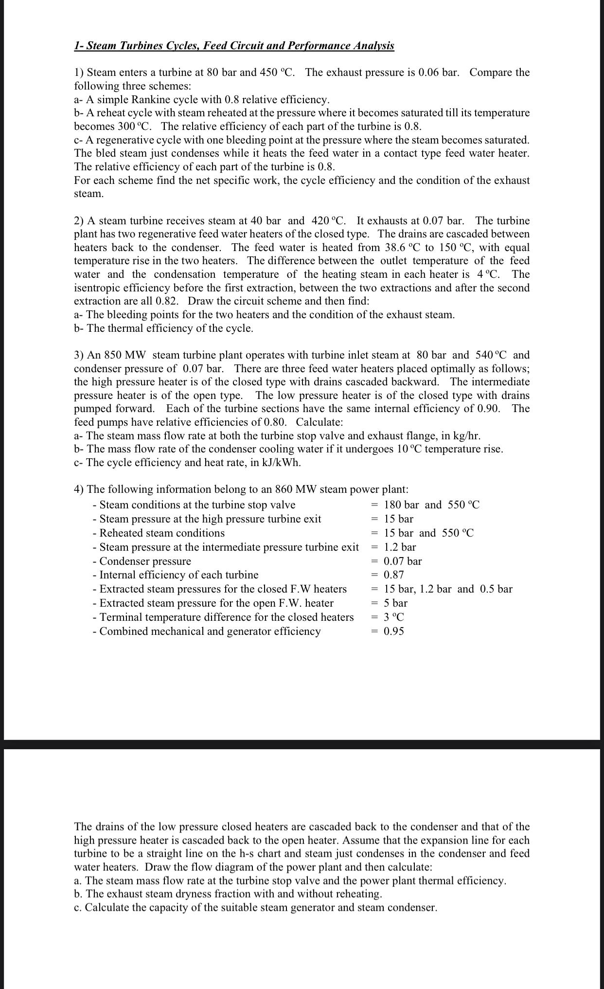
1-Steam Turbines Cycles, Feed Circuit and Performance Analysis 1) Steam enters a turbine at 80 bar and . The exhaust pressure is 0.06 bar. Compare the following three schemes: a- A simple Rankine cycle with 0.8 relative efficiency. b- A reheat cycle with steam reheated at the pressure where it becomes saturated till its temperature becomes . The relative efficiency of each part of the turbine is 0.8 . c- A regenerative cycle with one bleeding point at the pressure where the steam becomes saturated. The bled steam just condenses while it heats the feed water in a contact type feed water heater. The relative efficiency of each part of the turbine is 0.8 . For each scheme find the net specific work, the cycle efficiency and the condition of the exhaust steam. 2) A steam turbine receives steam at 40 bar and . It exhausts at 0.07 bar. The turbine plant has two regenerative feed water heaters of the closed type. The drains are cascaded between heaters back to the condenser. The feed water is heated from to , with equal temperature rise in the two heaters. The difference between the outlet temperature of the feed water and the condensation temperature of the heating steam in each heater is . The isentropic efficiency before the first extraction, between the two extractions and after the second extraction are all 0.82. Draw the circuit scheme and then find: a- The bleeding points for the two heaters and the condition of the exhaust steam. b- The thermal efficiency of the cycle. 3) An steam turbine plant operates with turbine inlet steam at 80 bar and and condenser pressure of 0.07 bar. There are three feed water heaters placed optimally as follows; the high pressure heater is of the closed type with drains cascaded backward. The intermediate pressure heater is of the open type. The low pressure heater is of the closed type with drains pumped forward. Each of the turbine sections have the same internal efficiency of 0.90 . The feed pumps have relative efficiencies of 0.80 . Calculate: a- The steam mass flow rate at both the turbine stop valve and exhaust flange, in . b- The mass flow rate of the condenser cooling water if it undergoes temperature rise. c- The cycle efficiency and heat rate, in . 4) The following information belong to an steam power plant: - Steam conditions at the turbine stop valve - Steam pressure at the high pressure turbine exit - Reheated steam conditions - Steam pressure at the intermediate pressure turbine exit - Condenser pressure - Internal efficiency of each turbine - Extracted steam pressures for the closed F.W heaters - Extracted steam pressure for the open F.W. heater - Terminal temperature difference for the closed heaters - Combined mechanical and generator efficiency The drains of the low pressure closed heaters are cascaded back to the condenser and that of the high pressure heater is cascaded back to the open heater. Assume that the expansion line for each turbine to be a straight line on the h-s chart and steam just condenses in the condenser and feed water heaters. Draw the flow diagram of the power plant and then calculate: a. The steam mass flow rate at the turbine stop valve and the power plant thermal efficiency. b. The exhaust steam dryness fraction with and without reheating. c. Calculate the capacity of the suitable steam generator and steam condenser.