(Solved): 1. Build the circuit in the logic diagram using the 7402 chip and the trainer. Reference the datashe ...
1. Build the circuit in the logic diagram using the 7402 chip and the trainer. Reference the datasheet to determine pinout of 7402 chip. Vcc for all theTTL chips will use the +5V power supply.
2. Build the circuit in the logic diagram using the 7400 chip and the trainer. Reference the datasheet to determine pinout of 7400 chip. Vcc for all theTTL chips will use the +5V power supply.
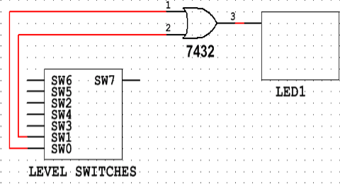
3. Turn off the trainer. Build the circuit in the logic diagram (Figure 2) using the 7432 chip and the trainer. Reference the datasheet to determine pinout of 7432chip. Vcc for all the TTL chips will use the +5V power supply.
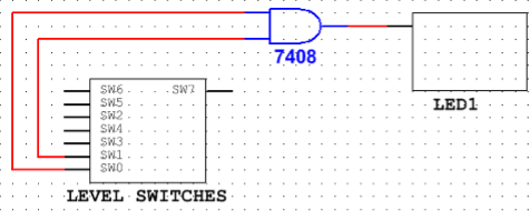
4. Build the circuit in the logic diagram (Figure 1) using the 7408 chip and the trainer. Reference the datasheet to determine pinout of 7408 chip. Vcc for all theTTL chips will use the +5V power supply

