Home /
Expert Answers /
Electrical Engineering /
1-build-and-test-a-1-bit-full-adder-in-multisim-a-construct-the-circuit-shown-in-fig-3-using-i-pa897
(Solved): 1. Build and test a 1-bit full adder in Multisim. (a) Construct the circuit shown in Fig. 3 using I ...

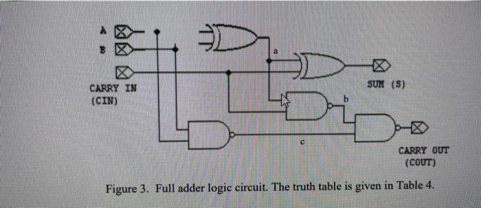
1. Build and test a 1-bit full adder in Multisim. (a) Construct the circuit shown in Fig. 3 using INTERACTIVE DIGITAL CONSTANT parts for the inputs and Probe parts to display the Sum and Carry Out. Include the schematic in your Pre-lab. (b) Apply all 8 input combinations and record the outputs \( \mathrm{S} \) and Corr in a truth table similar to Table 4. Are your results correct?
Figure 3. Full adder logic circuit. The truth table is given in Table \( 4 . \)